Water Jacketed Vat
Operator's Manual
Setup
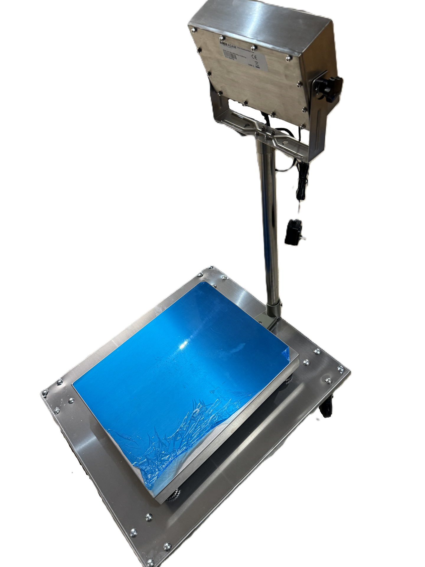
Dolly Setup
If you are using a dolly and/or scale, position it in the center so that it is evenly balanced and supported. Plug the scale into an open outlet. Calibrate per the manufacturer's recommendation. Refer to the operator's manual for the specific scale and dolly being used as it may vary.
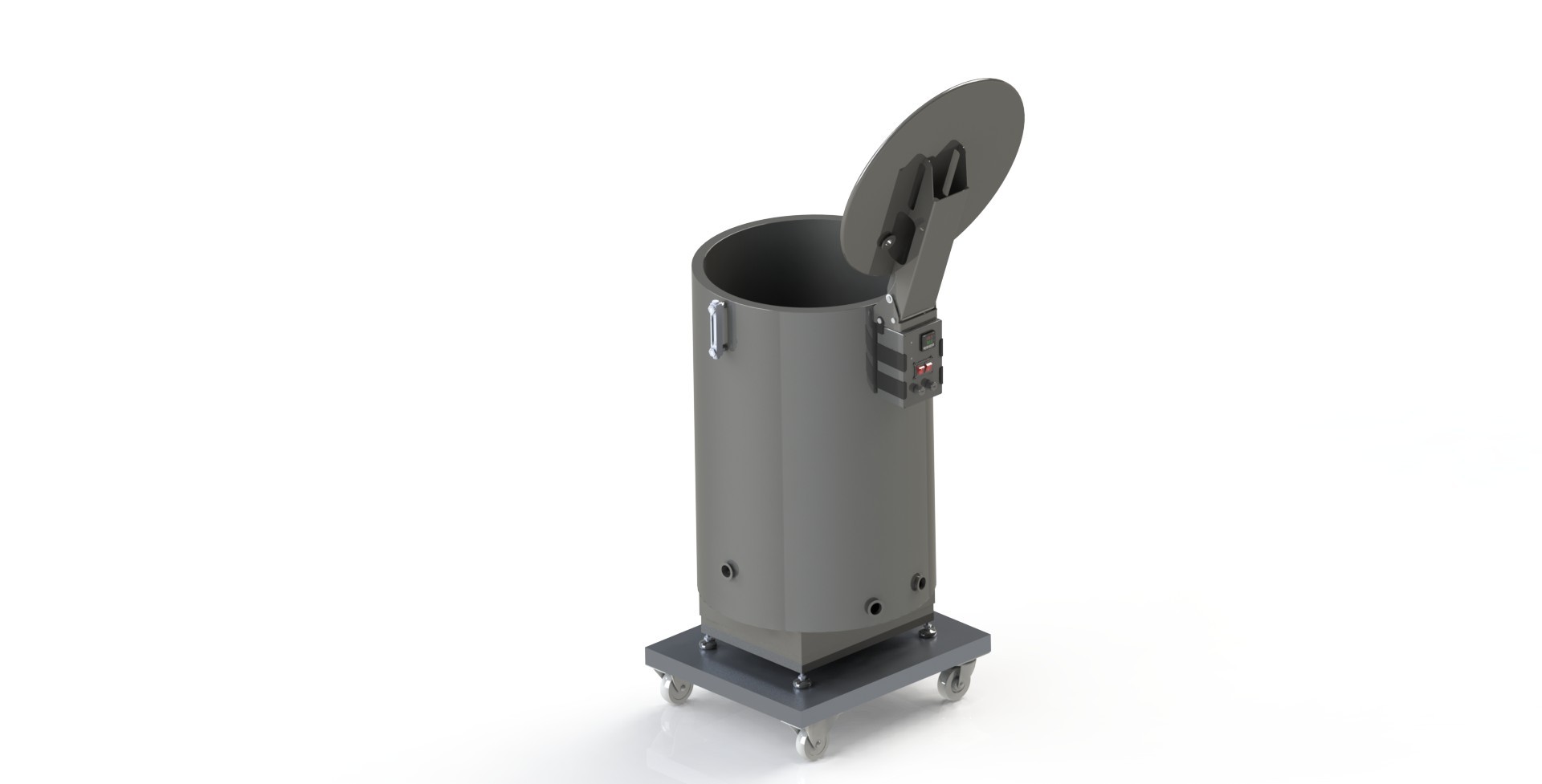
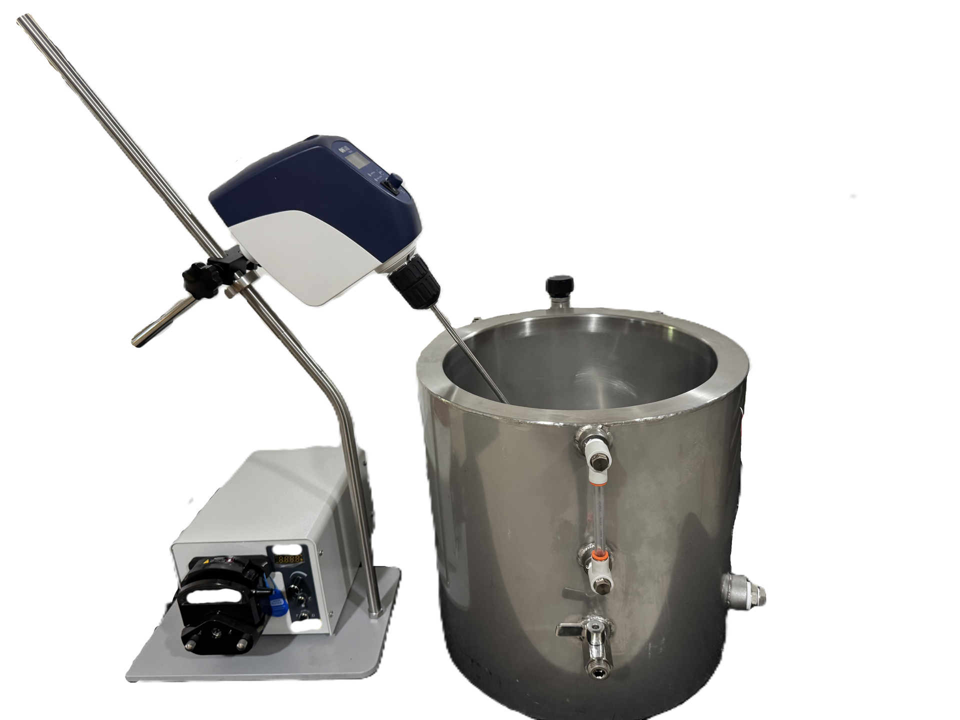
Tank Assembly
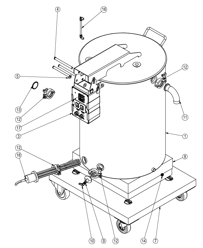
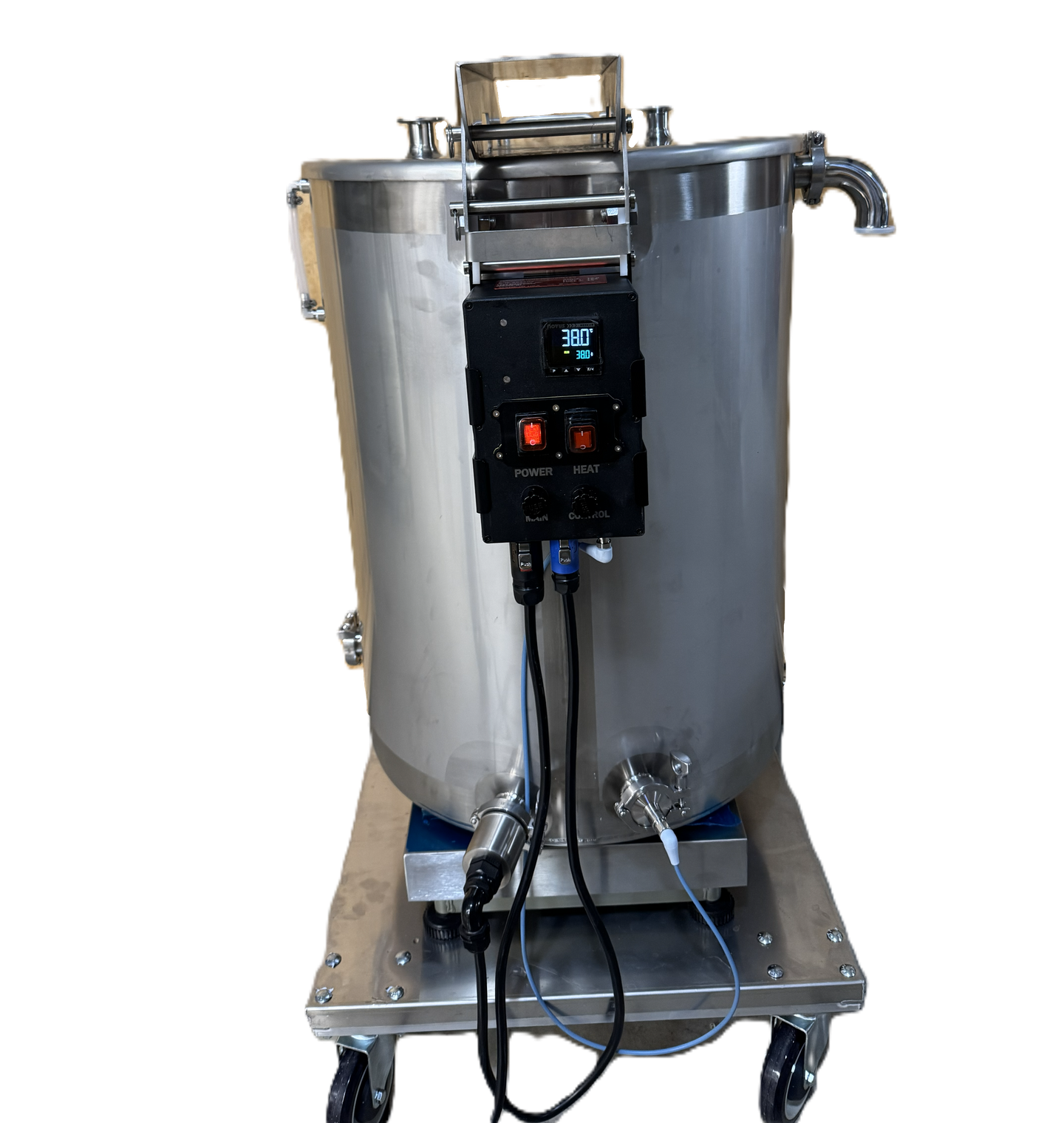
The tank (1) should be centered on the dolly (7) scale (8) assembly (if used) and aligned with the leveling tabs that are installed on the underside of the tank. The lid is secured with a clevis pin (4) and 4 PTFE washers (5) between the stainless components. An additional clevis pin is used as a tank stop, but can be removed if required for the application.
The temperature controller (3) can be mounted to the hinge with a clevis pin, or it maybe be positioned elsewhere are required for the application.
Item | Description | Quantity |
|---|---|---|
1 | Water Jacket Vat | 1 |
3 | Temperature Controller | 1 |
4 | Clevis Pin | 3 |
5 | PTFE Washer | 4 |
7 | Dolly | 1 |
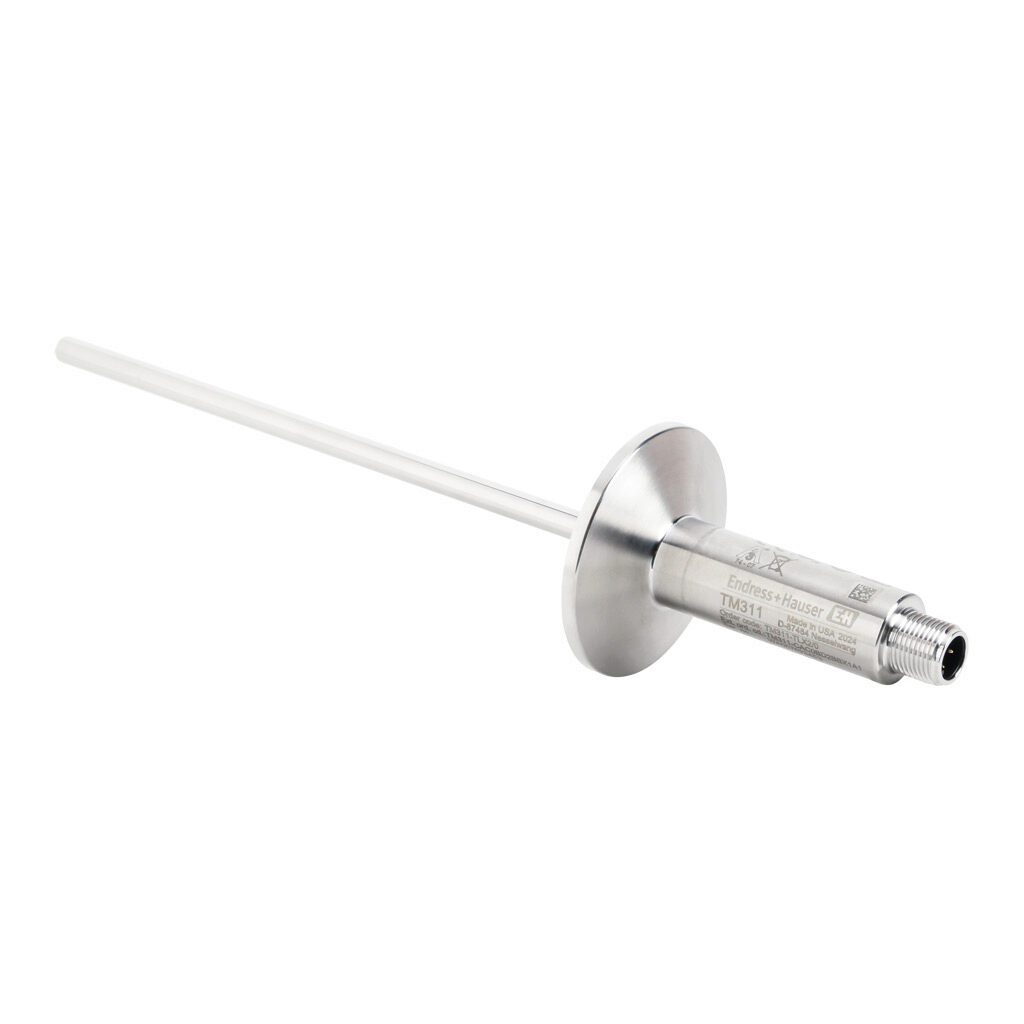
9 | Temperature Probe | 1 |
10 | Temp Probe Cable | 1 |
11 | Stainless Filling Elbow | 1 |
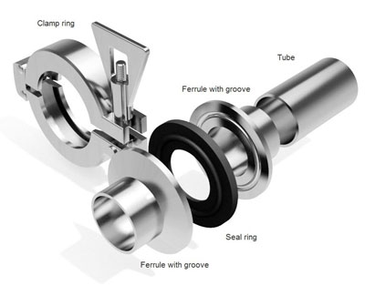
12 | Tri-Clamp | 4 |
13 | Stainless Pipe Cap | 1 |
14 | Drain Plug | 1 |
16 | Sight Tube | 1 |
17 | Stainless Cotter Pin | 3 |
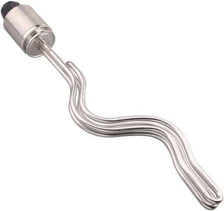
18 | Heating Element | 1 |
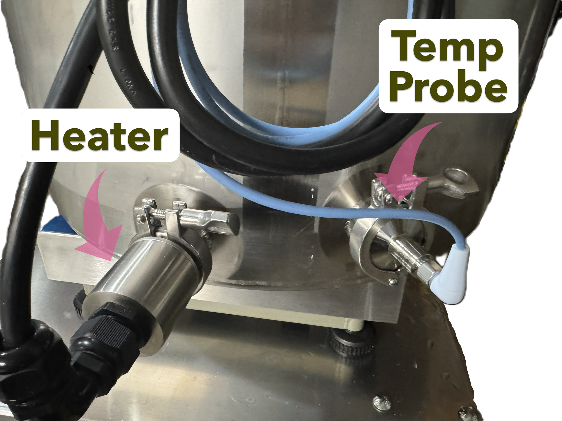
Insert the heating element (18) and temperature probe (9) into the appropriate fittings. The heater should be in the lower fitting, and the temperature probe should be slightly higher (as shown). Both should be secured with a tri-clamp fitting (12) as shown.
Install the jacket drain plug (14), using PTFE tape to seal the threads. Install the tank cap (13) using a tri-clamp fitting (12).
The filling elbow (11) should be used when filling the jacket with RO filtered water. Fill the jacket up until it is 1/2 way up the sight tube (16).


Mixer Setup
For proper performance, some type of mixing must be utilized. If a powder based solution is being utilized, a mechanical mixer is preferred. Alternatively, a circulation (pump) style mixer can also be utilized.
With a circulation pump, the solution should be drawn from the bottom and deposited towards the top to reduce powder settling to the bottom, while being careful to not induce excessive air into the mixture.
The preferred blade for mechanical mixing is a pitched blade or hydrofoil pushing flow in a down direction and offset to the side.
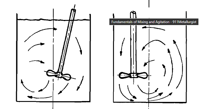
It is up to the end user and the specific application to determine the proper time and duration for complete mixing within the user's setup.
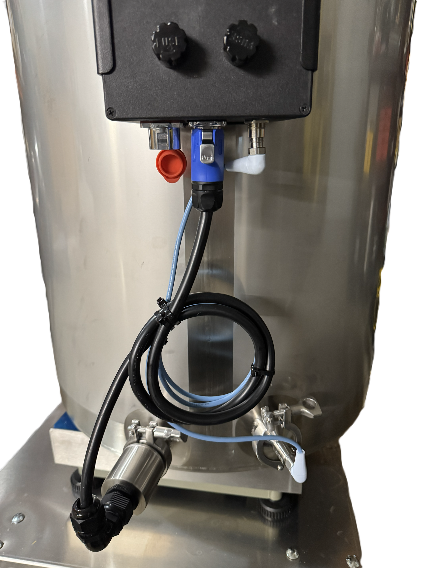
Electrical Assembly
The controller comes with a 10' power cord. If a longer lead is required, a grounded extension cord with minimum 12AWG conductors is required. In addition, the circuit should have a ground-fault circuit interrupter (GFCI) installed. An inline GFCI is adequate. The connections are shown below:
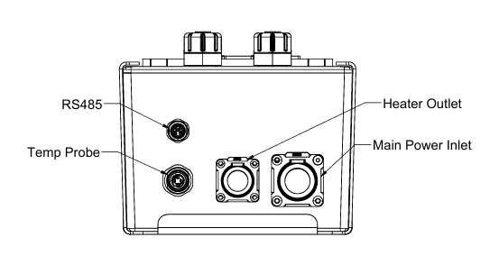
Main power, heater and temperature probe should be connected as shown.
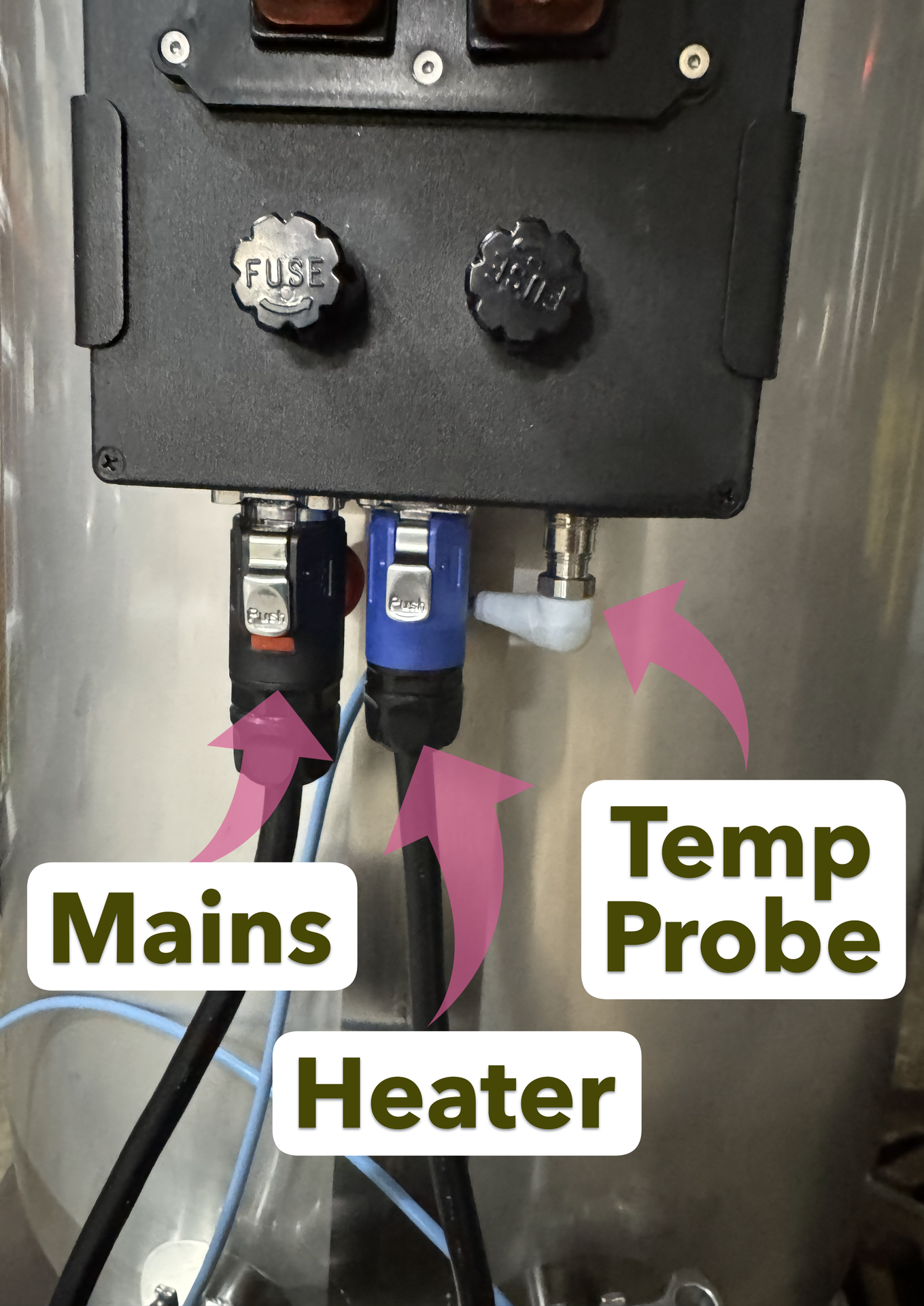
Reference the controller name plate for power and fuse specifications. Specifications may vary by application (voltage, amperage, fuse size, etc.).

Operation
An advanced PID control algorithm is used to maintain the mixing vat's temperature.
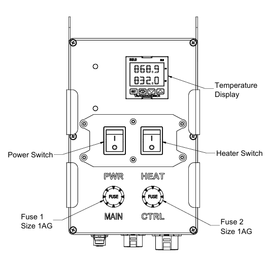
There are two switches for operation, “Power” and “Heat”. The main “Power” switch controls the power for the entire system. Always turn off the power switch when connecting or disconnecting the controller from the main power source or for service and maintenance. The switch will be illuminated red when power is enabled to the controller.
The “Heat” switch, when turned off will disconnect the vat heater from the power source and prevent the heater from functioning, while allowing operation of the controller such as configuration and temperature measurement. The switch will be illuminated red when the heater is powered on.
Additionally, operation parameters Ctr = "Auto" and Run = "Yes" must be setup for proper heating to occur.

Display
After the electrical installation has been completed (see SETUP) and the unit has been turned on, the controller will display the software version number for 2-3 seconds, followed by the Indication Screen. The Indication Screen will show the PV (Process Variable) and SP (Setpoint) values in addition to flags that notify specific conditions of the controller and monitored processes. After that, it will display the Indication Screen. It shows the PV (Process Variable) and SP (Setpoint) values and flags that inform specific conditions of the controller and monitored process. Controller front panel and basic display information shown below.
Display Information
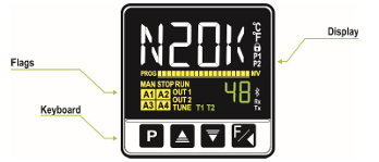
The display elements are listed below:
• Main Display: The Indication screen, in white, displays the PV (Process Variable) value. When in configuration, it shows the identifying symbols (mnemonics) of the parameters that must be set.
• SP/Parameters Display: The Indication screen, in green, displays the SP (Setpoint) value. When in configuration, it shows the values set for the various parameters.
• PROG Flag: Indicates that a program is running.
• MAN Flag: Controller is in Manual Control mode (CTR = MAN).
• STOP Flag: Control is disabled (RUN = No). The device is not in operation.
• RUN Flag: Control is enabled (RUN = YES). The device it is in operation.
• OUT1 Flag: Indicates the condition of outputs A and B or modules outputs.
• TUNE Flag: Auto-tuning process is in progress.
• A1, A2, A3, and A4 Flags: Indicates that there are alarm events.
• °C Flag: Temperature measurement was set in Celsius.
• °F Flag: Temperature measurement was set in Fahrenheit.
• 🔒 Flag: Indicates that configuration protection is enabled.
• T1 and T2 Flags: Indicates that there is a timer configured.
• Bluetooth Flag: Indicates that the controller is connected to the QuickTune Mobile application.
• Rx/Tx Flags: Flashes whenever the controller exchanges data with the communication network.
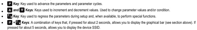
Keyboard
The front panel has the following keys:
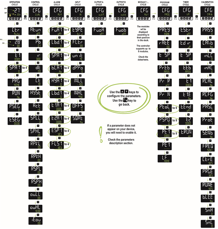
Configuration
The configuration parameters have been gathered into affinity groups, called Cycles. As shown in the figure below, there is the Operation Cycle and the Configuration Cycles, composed of Control, Alarms, Input, Output A, Output B, Modules (1 to 8), Programs, Timer, and Calibration:
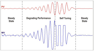
Auto Tuning
Auto-adaptive tuning is initiated by the controller whenever there is significant deviation from the previous tuning. To activate performance supervision and auto-adaptive tuning, the ATUN parameter must be set (Ctrl >> Atun) in SELF, rSLF or tGHT mode. During auto-adaptive tuning, the behavior of the controller depends on its performance. If the deviation is minimal the tuning correction will be hardly noticed, but if the deviation is significant the auto-adaptative tuning is similar to the auto-tuning mode, applying the minimum and maximum performance to the process in ON/OFF control. The process can be seen below:
Press  for 3 seconds to
access the Ctrl configuration cycle and initiate tuning. Select the tuning type
in the ATUN parameter:
for 3 seconds to
access the Ctrl configuration cycle and initiate tuning. Select the tuning type
in the ATUN parameter:
oFF
The controller does not perform auto-tuning or auto-adaptive tuning. The PID parameters will not be automatically determined or optimized by the controller.
FAST
The controller will perform the auto-tuning process only once, returning to oFF mode after it is finished. In this mode, the tuning will be completed in less time, but will not be as precise as in FULL mode.
FULL
This mode performs the same process as FAST mode, although the tuning is more precise and slower, resulting in better PID control performance.
SELF
The process performance is monitored, and auto-adaptive tuning will start whenever the performance becomes unsatisfactory. After an adjustment cycle, the controller will start collecting data about the process. This helps it to create a reference, which is used to assess the need for further adjustments. This phase is proportional to the response time of the process.
RSLF
The controller performs the auto-tuning process and returns to SELF mode. Normally, this mode is used to force immediate auto-tuning of a controller that is operating in SELF mode.
tGHt
Like SELF mode. In addition to auto-adaptive tuning, performs auto-tuning whenever the controller is set to RUN = YES or when the controller is powered up.
Whenever the ATUN parameter is changed to a value other than OFF, auto-tuning will be immediately started by the controller (if the controller is not set to RUN = YES, tuning will start when it transitions to this condition). For the auto-adaptive tuning to work properly, it is essential to perform auto-tuning. During the tuning process, the TUNE indicator will remain lit in the display.
If the tuning process does not result in satisfactory control, the table below presents guidelines on how to correct the process behavior:
Parameter | Verified Problem | Solution | ||||
|---|---|---|---|---|---|---|
Proportional Band |
|
| ||||
Integral Rate |
|
| ||||
Derivative Time |
|
|
Calibration
If the displayed temperature is not in alignment with the actual temperature, the temperature probe may require calibrating.
Once temperature equilibrium has been attained and measured, hold until the Input Cycle is shown (In). Press  seven times until the offset parameter (OFFS) is displayed. Adjust the value so that the measured value matches the displayed value. For example, if the measured value is 22.0 degrees and the displayed value is 22.5 degrees, increase the OFFS value by 0.5 degrees.
Alarms
Alarms are configured for a deviation of +/- 2 degrees, but are blocked on startup. Once the vat has reached operating temperature, any deviation greater than the configured amount will trigger an alarm display (A1, A2, A3 or A4). Alarms can be configured in the ALM configuration cycle. (CFG>>ALM>>Fu.A1, Fu.A2, Fu.A3, Fu.A4).
- oFF: Disabled
- Lo: Minimum Value Alarm (Low)
- Hi: Maximum Value Alarm (High)
- *diF: Differential Value Alarm (Differential)
- diF.L: Differential Minimum Value Alarm (Differential Low)
- diF.H: Differential Maximum Value Alarm (Differential High)
- i.Err: Input Error (Input Error)
- rS: Event Alarm (Ramp and Soak)
- End.t: End of Soak (End of Level)
- Lbd: Loop Break Detection
*Default alarm configuration
Cleaning & Maintenance
Interval | Maintenance Items |
|---|---|
Daily |
|
Weekly |
|
Monthly |
|
- All stainless steel components may be cleaned and sanitized with alcohol-based cleaners. Avoid chlorine or bleach solutions.
- The controller, including plastic and rubber components, should be cleaned with mild cleaners such as dish detergent or Simple Green.
Internal circuit protection is provided by 1AG (1/4") fuses. Fuses should be replaced with 1AG fuses of the same amperage rating. The amperage rating will be specified on the controller label and will never exceed 20 amps. The controller should always be plugged into a functioning GFCI outlet with proper circuit protection according to local regulations.
Troubleshooting
Issue | Likely Source | Items to check |
|---|---|---|
Controller display is off | No power to the controller |
|
Vat is not heating | No power to the heater |
|
Display is showing "----" | Sensor input broken wires |
|
Display is showing "UUUU" | Sensor input short circuit |
|
Temperature is not stable | Environmental Disturbances Incorrect tuning parameters |
|
Temperature is not accurate | Incorrect Measurement |
|
Vat is leaking | Leaky Fitting |
|
Table of Revisions
Revision | Date | Updates |
|---|---|---|
A | 12/10/2025 | Initial Release |